Installation Guide for Plyboo Panels
-
- Reveal
- Linear Line
- Linear Sound
- Plyboo Sound
- Louver
- Louver Sound
1.0 General Description:
Plyboo® paneling systems by Smith & Fong Co. are offered in many configurations to suit various wall and ceiling installation requirements. The architectural panels use distinctive patterns milled into the face ply of the panels to expose the panel’s core layer, creating fascinating visual and tactile patterns by juxtaposing the core and surface layers of the panels.
Taking advantage of bamboo’s innate strength and flexibility, Plyboo architectural panels are manufactured using Realcore® plywood, our proprietary 3-ply bamboo plywood panels manufactured to meet stringent specifications for wall and ceiling applications.
Plyboo wall and ceiling paneling systems have been well received by architectural and design professionals since their introduction in 2012. Our panels have been specified and installed in numerous locations, and have quickly become known for their inherent aesthetic and functional qualities, already earning numerous industry awards and recognition.
This guide is intended to provide basic details and characteristics for each type of panel design, with general guidance for installation and use of the panels. We also discuss one commonly used installation method using cleats in a suspension system that is intended to accommodate movement in these flexible panels. A suspension system, for example the Monarch® Z-Clip system that is discussed here, typically works much like any other cleat for an installation without screwing into the face ply of a panel.
Though many customers prefer installation with French cleats due to its inherent visual and structural effectiveness, numerous other installation systems may be utilized at the discretion of the installer and subject to job requirements. We provide this advice for use at your discretion, and our advice is neither intended nor should be used as a substitute for an architect’s or engineer’s plan, in particular because our advice is based on general information and cannot take into account the unique requirements or conditions for each installation, including for example actual on-site conditions, local code requirements, and all other requirements that may be applicable to a particular installation.
1.1 Product Description:
All Plyboo panels described here are generally known as the Reveal, Linear Line, and Sound panels, with the product group referred to as RLS.
All Plyboo RLS panels are manufactured of 100% bamboo, typically using RealCore plywood, a 3-ply bamboo plywood product featuring a bi-directional core that is specially selected for visual consistency through the core layer. Smith & Fong developed RealCore plywood specifically to work with our RLS panel designs to allow the use of flexible and curved applications.
Our panels typically feature design patterns carved into the face ply, with relief cuts on the back side of the panel to provide balance and allow for flexibility. This design permits RLS panels to deflect from flat across the width or length of the panels. Our RLS panels can be quite flexible, with the degree of flexibility varying with the design, with some panels being flexible enough to easily accommodate many unusual installations, including to wrap around columns or other curved support surfaces. Nevertheless, the same RLS panels are also designed to snap rigid and flat when properly installed using appropriate fasteners.
Upon receiving the panels, you should note that the panels will not be perfectly flat, and as explained further in Section 1.1.3. on panel “Storage”, the panels in fact may have some residual tension, causing them to bend or curl and not lay flat out of the box. This is part of the inherently flexible nature of the panels, with the panels intended to snap flat upon installation using your chosen fastener system.
1.1.1 REVEAL Panels are carved with dramatic patterns aggressively carved into the face or top layer of the panel. Because of these bold designs, the panels feature striking visual presentations with much of the face layer removed to expose the bamboo core layers to create a striking presentation.
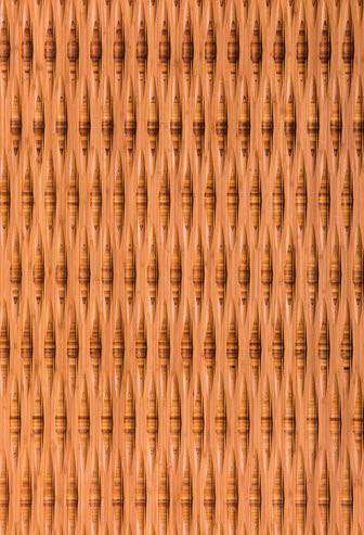
Plyboo REVEAL, Style C1
The face ply of REVEAL panels are carved with deep patterns, with a shallow grid milled into the back of the panels to relieve strain. Because so much of the face ply is removed during carving, the panels can readily respond to changes in ambient environmental conditions.
1.1.2 LINEAR LINE Panels feature carved lines of various thicknesses running the length of the panels, cutting down to the core layer to reveal the bamboo grain pattern. These panels juxtapose the subtle texture and grain pattern of the bamboo core with the dramatic grooves carved into the face ply, both harmonizing the structured vertical grooves with the bamboo grain pattern, as well as creating a subtle contrast between the patterns. Because these are repeating patterns, a consistent, seamless pattern can be achieved across multiple panels when installed properly.
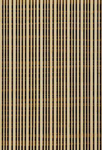
Plyboo Linear Line, Style LL1
1.1.3 PLYBOO SOUND Panels feature perforations through the panel so that sound waves can travel through the panel and be dissipated by the backing material. We offer a compatible 1” thick fiberglass sound attenuation backing material for this type of acoustical abatement, and when installed with this type of backing material, the panels provide significant sound attenuation qualities.
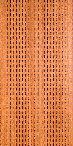
Plyboo Sound, Style C1
Please note that the perforations in these panels may visually expose portions of the supporting installation hardware (e.g., Monarch® Z clips or similar). Hardware should be painted black or to match wall color to minimize visibility. Additional installation room behind the panel should be provided when using sound absorption backing material.
1.1.4 LINEAR SOUND panels have a similar grooved pattern to the Linear Line, but with the grooves undulating in depth as they are carved into the core layer while running the length of the panel. Additionally, to help with sound attenuation, the panels also feature perforations through the panel in varying but regular patterns. These carved patterns consistently repeat across the panel, such as to have a consistent pattern across multiple panels when arrayed and installed properly.
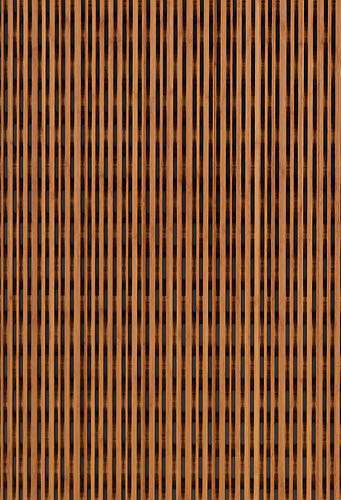
Plyboo Linear Sound, Style LS-11
The juxtaposition of the grooves and the perforations, arrayed against the subtle bamboo pattern of the core layer, creates a dramatic visual moiré pattern. Because of the intricate and extensive millwork in these panels, the panels are quite flexible across the width of the panels, and indeed may even be installed along gentle curves.
1.1.5 LOUVER This series of architectural wall panels takes its inspiration from angled fins which capture light and create dimension. Panels can be aligned or offset. Louver designs can be used in a single design, or different designs can be used together to create ceilings and walls that explore depth, structure and line weight.
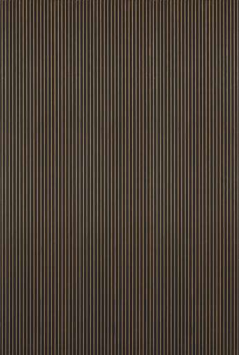
Plyboo Louver Butterfly in Gold Noir
1.1.6 LOUVER SOUND Panels can be aligned or offset. Louver designs can be used in a single design, or different designs can be used together to create ceilings and walls that explore depth, structure and line weight. Perforation offers acoustical sound reduction as well. Louver is made from Realcore which is proprietary to Plyboo and ensures quality of implementation.
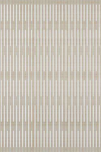
Plyboo Louver Butterfly Sound in Mist
1.2 Panel Sizing & Dimensional Change:
Our panels are typically offered in a nominal 47 ¾ x 95 ¾”, but are also available in other custom sizes to suit your particular installation needs. **Please contact us with your inquiries for custom sizing of any panel.**
Using our computer numeric control (CNC) manufacturing processes, we maintain dimensional control over the panels through the manufacturing process, and further perform several quality control checks during the manufacturing process to assure correct sizing. Nevertheless, because of the hygroscopic tendencies of wooden products, it is imperative that panels be stored in appropriate environmental conditions and be protected against dimensional change caused by seasonal variations in ambient environmental conditions.
If you encounter excessively low relative humidity, resulting in panel shrinkage, please consider installing an appropriate reveal between panels. Architectural Woodwork Institute (AWI) standards reference a 1/16 th inch reveal for use in panel installation, and the use of a 1/16th reveal between panels should not affect panel visual performance while allowing for adequate dimensional change as relative humidity varies through seasonal changes.
1.3 Site Conditions, Storage & Handling:
1.3.1 Packing: Your panels are packed on an oversize pallet, with each panel surrounded with a 1” thick perimeter of packing hardboard or OSB helping to prevent damage to the panels while in transit.
PLEASE NOTE: Damage to the packing hardboard or OSB material is not a cause for rejecting the pallet as the panels are typically protected inside the packing. As noted in the next section however, please make sure to inspect both the product and packaging, and to document any damage to either packaging or products during shipping.
1.3.2 Inspect Upon Delivery: Given our extensive packaging, damage to our panels during shipping should be rare, but please carefully inspect your package and note any damage to the product or packaging during shipping.
Upon receipt of the panels, please promptly open the shipping pallet and inspect the panels. If you notice any damage to the packaging pallet or any product, please notify the carrier immediately and, prior to any acceptance of the delivered package, note the extent of the damage on the waybill or transit documentation given you by the carrier.
Please note that the limited warranty applicable to these products does not cover any damage caused during shipping or transit and you must make a claim for any such damage directly with the carrier.
1.3.3 Storage: Panels should always be stored in a dry, clean, and temperature-controlled environment. Please do not allow panels to be stored outside, or exposed to exterior environmental conditions because any such exposure will void your limited warranty. It is best to store the panels in the original factory pallet packaging in a flat horizontal position. Do not expose the panels to extreme temperatures or sources of moisture, and do not store in unconditioned spaces with humidity exceeding 55% or lower than 35% RH, or temperatures lower than 55°F or greater than 85°F.
Please note that many of these panels, and in particular the panels with aggressive face-ply carving such as the Reveal panels, will tend to curl, or deflect from flat, in response to ambient environmental changes. Once this type of movement has started, the force necessary to correct it will be significantly greater than the force required to keep them flat in the first place. As such, please store these panels in the original pallet prior to installation.
1.3.4 Acclimatization: For a successful installation, it is vitally imperative that the installation site is fully enclosed, with HVAC running, and has been acclimatized to the ambient temperature and humidity conditions that will be prevailing once the space occupied. This is one of the most important criteria for having a successful installation, and one of the most common reasons for a failed installation. Note: Please remove any pallet shrink wrap to allow the acclimatization process to begin.
All windows and doors should be in place in the installation space, with all HVAC systems installed and operable to maintain proper temperature and humidity conditions before, during, and after installation of the panels. Whether at the job site or in the millwork shop, our panels should be stored in and acclimatized in spaces once the building is wholly enclosed and HVAC systems continuously functioning.
To acclimatize the panels to the site conditions, you must maintain an indoor environment between 55 – 85°F (13 – 30°C), and relative humidity of 35% – 55%, for a minimum of 7 days prior to installation, with such conditions maintained following installation.
1.3.5 Maintain Adequate Environmental Controls: Like all wood products, our panels are hygroscopic in nature and, depending on the ambient environmental conditions, can readily absorb, retain, and dissipate moisture. Such wooden products undergo dimensional change, expanding with absorption, and shrinking with dissipation of moisture. Because of this hygroscopic characteristic, maintaining adequate environmental controls is probably the most important factor affecting the performance and service life of these panels.
Please avoid all contact with moisture, and immediately dry any panel surfaces that has come in contact with moisture. Similarly, avoid contact with heat sources, such as lights or HVAC registers, as direct heat will damage the panels.
1.4 Color
Our panels are typically available in several solid and duotone colors and can be finished with natural oil- or water-based finishes. We can also provide many finishes that are customer specified to match architectural control samples.
Please check your panels for color and tone when you receive them. Variations in color and tone, as well as in grain, are typical to wooden products. Please take care to arrange and install your panels while considering maximal visual consistency through the panels’ arrangement.
Please note that like other natural products, our panel products have a tendency to darken over time as they are exposed to sunlight.
2.0 Working with Panels:
2.1 Tools & Cutting the Panels: Our panels must be cut with an 80 Tooth Carbide blade, or better. To avoid blow-outs on (e.g., while crosscutting a panel,) please raise the saw blade allowing the blade to cut down on the panel. Please take care to cut the panels slowly. Touch up with a natural oil finish can be purchased directly from Smith & Fong to address any edges as needed.
For visible cuts, for example cutouts for outlets or switches, we recommend the use of a spiral saw (e.g., a RotoZip) which can make both plunge cuts as well as cuts in from the edge of a panel, with typically clean and neat resulting edges.
Please always exercise all proper caution when working with power tools, including to protect against environmental hazards such as airborne dust.
2.2 Panel Arrangement for Consistent Color: Our panels may exhibit natural variations in color and grain from one panel to the next, or one production lot to the next. Further, panels are often ordered in various lots, and the finish may vary by lots.
Prior to installation, we recommend that you arrange the panels on the installation surface based on your personal preferences to minimize and harmonize the visual appearance of any such natural variation. To further help provide consistency across various lots, please order the entire job at one time, or notify us of panels being installed to match a previous finish run. If you feel you have the wrong color, or your panels have an error, please notify us immediately, and in all events within 14-days of receipt of panels.
2.3 Panel Alignment for Consistent Pattern: Please carefully note that our panels have defined top, bottom, left, and right edges, and will need to be properly oriented for successful installation. This is vitally important for panels that are intended to affect a repeating, seamless pattern when installed properly (e.g., Linear Sound panels.)
To help you define proper orientation for a panel, our production team will mark a small “X” on the back of each panel to identify the top of the panel. Proper orientation is of vital importance for achieving a seamless pattern, and proper orientation must be maintained to successfully align a repeating pattern for ceilings and walls.
Referring to the Linear Sound panels for illustrative purposes, please see Diagram 1 for how the panels are “X” marked to help identify proper orientation. To identify the top edge for the Linear Sound panel, first identify the small “X” marked on back of the panel. The top “X” should be joined to a non-X bottom and so on, creating a smooth undulating flow of the panel cores.
DIAGRAM 1
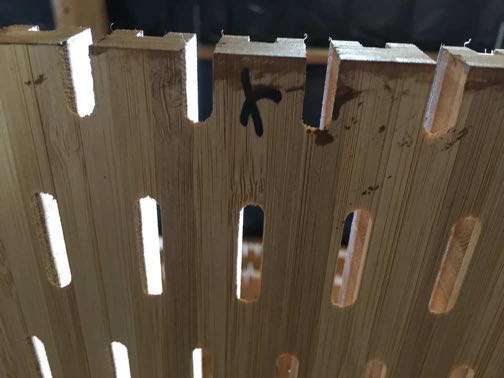
2.3.1 Tips for Alignment of Multiple Panels: panel pattern orientation may not be easily discernible when standing close to a panel. To check alignment from panel to panel (e.g., no “X” is present or has been cut off) please stand panels side to side, step a few feet back to allow the pattern wavelength (e.g., in the valley channels of a Linear Sound panel) to become obvious.
With patterns that repeat seamlessly across panels, we highly recommend taking the appropriate time to unpack two or more panels and to line them up for a side-by-side evaluation and trial arrangements until a seamless panel placement is identified with the high and low patterns arranged in a fluid and continuous pattern across panels (with the high pattern corresponding to the peak of the wave form feature of the panels, and low pattern corresponding to the valleys of the wave form feature of the panels.)
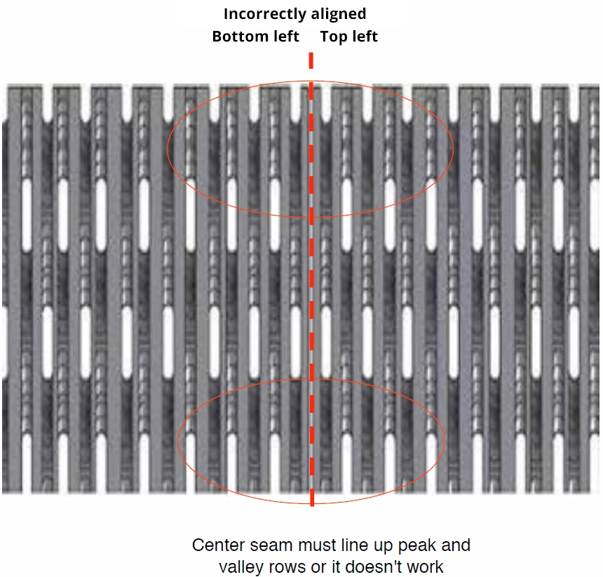
If the identified left- and right-side of a panel are reversed, the fluid wave pattern of the design will be interrupted. It is very important to keep the panels aligned and consistent with the pattern running left to right upon installation. These panels display various rolling high and low lines to create their distinctive visual effects. It is important that the panels are arranged such that side to side you have an alternating valley (low) and peak (high). Regardless of the origin of the panel, starting on a high peak or a low valley, you should never have two adjacent lows or two adjacent highs . If you notice such an arrangement, your panels will need to be realigned for proper installation as shown in Diagram 2.
DIAGRAM 2
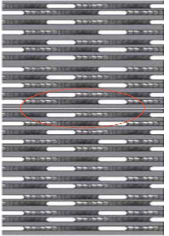
Circle shows two 1/8? outer high edges forming 1/4? joint
We recommend against cutting the edges of panels to remove the 1/8” high ribbing because this high ribbing is specifically provided as a transition element to the next panel, forming a seamless installation at the joints when properly installed. Removal of this 1/8” high edge allows the panel to dive down under the next panel creating an obvious and unsightly seam.
2.3.2 Tips for Vertical Alignment of Multiple Panels: When arrayed vertically, the top and bottom panels with repeating patterns are joined as high-high and low-low so that the undulation of the wave pattern is continuous, uninterrupted. When aligning a top panel to a bottom panel the pattern should meet high to high before continuing to a low to low alignment between the top and bottom panels, hence allowing a fluid and undulating rolling pattern vertically up and down, and horizontally across multiple panels. Please see Diagrams 3 and 4 below for an illustration of how the panels should be vertically oriented in this way.
Please note, when joining a high (peak) top to a low (valley) bottom, your panel is likely rotated 180 degrees. Your panel will look odd as it will not continue the gently sloping wave forms in high to high sloping form, but display an abrupt jump from high to a low. Please see Diagrams 5 and 6 for illustrations of incorrect panel alignments that must be avoided.
DIAGRAM 3
Installation Guidelines for Linear Sound Panels from Plyboo by Smith&Fong
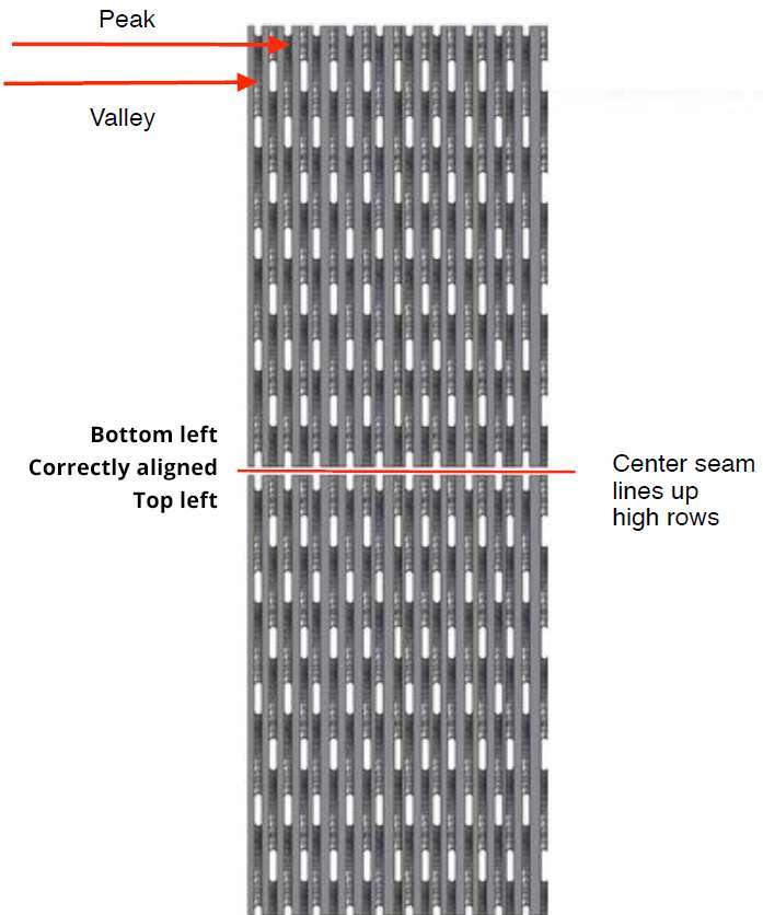
DIAGRAM 4
Installation Guidelines for Linear Sound Panels from Plyboo by Smith&Fong
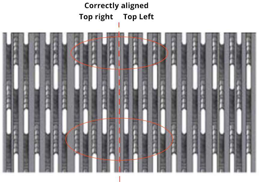
DIAGRAM 5
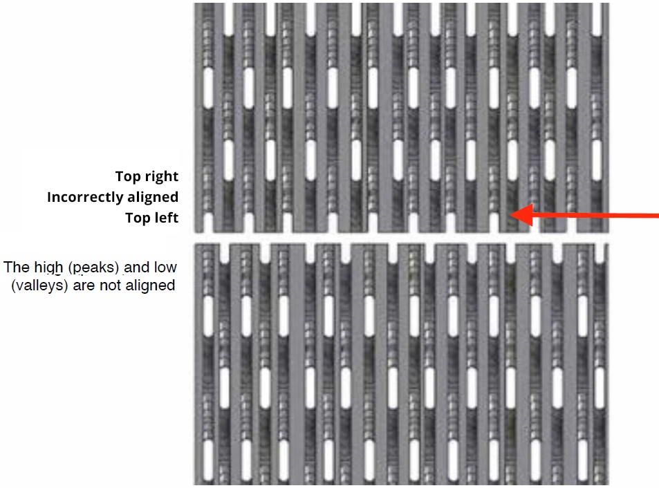
DIAGRAM 6
3.0 Installation Example Using the Monarch® Z Clip Suspension System
General Installation Notes: Pound for pound, Plyboo RLS panels have a higher tensile strength than steel. Any installation system that you use must be SECURELY ATTACHED TO THE WALL PANELS AND PROPERLY MOUNTED TO WALL STUDS OR OTHER STRUCTURAL MEMBERS CAPABLE OF SUPPORTING THE WALL PANELS. Never attempt any installation by simply gluing the panels, or the installation system, to the wall surface.
Prior to installation, please assure that your installation surfaces are true and flat, and are capable of supporting the architectural wall paneling installation system and panels. If your wall surfaces are not flat, consider using furring strips or the like to make sure the panels are installed on a uniformly even and flat surface.
Plyboo panels may be installed using any number of fastener types, including mechanical fasteners such as screws, or suspension type installation systems such as French cleats and the like. Because of their greater knowledge of particular site conditions, installation requirements, and the like, we defer to installers, architects, and other parties responsible for rendering installation services, including to identify and specify the ultimate choice of fasteners for the particular installation.
Many of our customers have great success installing our panels using suspension installation systems (e.g., French cleats) which continue to be the most common installation system for many paneling systems. Although mechanical fasteners such as screws are also used for installation, including in conjunction with or as part of other installation systems, special care must be taken when using mechanical fasteners, for example to pre-drill any screws placed in the face ply, and to avoid placing screws so as to compromise a panel’s structural integrity.
Monarch® Z-Clips and other forms of cleats providing a suspension installation system have become an industry-preferred method installation system because of their ease of use, and flexibility to accommodate various installations that allow panels to move in response to ordinary changes in ambient environmental conditions such as heat and humidity. Although mechanical fasteners may be used to install panels, special care must be taken not to hinder panel movement in response to ambient environmental changes.
Regardless of the type of installation system you ultimately choose, please always remember that it’s always best to “measure twice, but cut once,” specially for fastener placement.
Inappropriately placed fasteners of any type can exert unequal pressure on the panels, causing excessive or uneven panel movements during periods of dimensional change due to ambient environmental changes, or even causing cracks or other structural failures.
3.1 Monarch® Z-Clips – Suspension Installation System:
We recommend that prior to any installation you review various instructional material available through the Monarch Metal webpage www.monarchmetal.com for detailed specifications and instructions for use of various Z Clips as may be appropriate for your particular installation needs. Monarch also provides a short video generally displaying various elements of the Monarch Z Clip suspension system for installation of wall panels. See Diagram below for a general overview:
Monarch makes many types of Z Clips to accommodate a range of suspension systems. Although the ultimate choice of the installation system used is subject to the installer’s discretion, many customers typically rely on the Monarch like Z-Clip MF625 in installations (see Diagram below). Please see the Monarch website for the whole range of Monarch Z Clip options available prior to finalizing your choice.
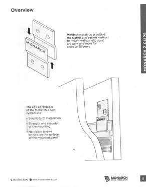
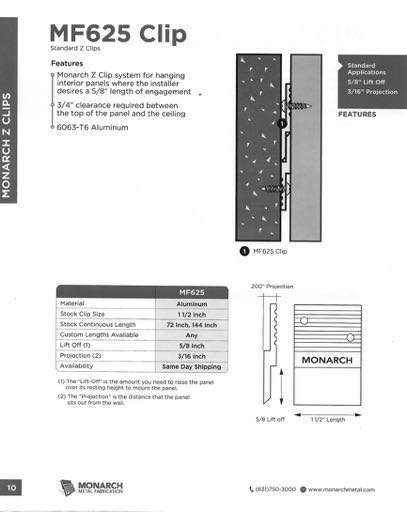
Monarch typically recommends using twelve (12) stock-length Z Clips (typically about 2” in length) evenly spaced across the width of each panel, and for some installations this may be the preferred method. But Z Clips are also available in many other lengths and may be cut to size and drilled on site as required. In many cases, Plyboo panels may be installed using four (4) continuous length Z Clips, each approximately 42” in length, evenly spaced across the back of a panel and spanning the width. Each of these “Z-bars” may further be painted to facilitate a hidden suspension system.
The Z-bar continuous length clips can come with pre-drilled screw holes, and additional holes may be made in the field by drilling through the aluminum Z-bar as needed to align with the optimal screw hold positions on the back of the Plyboo panel, with a minimum of 6 screws per 42” Z-bar continuous length clip being used. The optimal screw hold position on the back of the Linear Sound Panel is a point centered between both the horizontal and vertical perforation cuts of the particular design.
3.2 Installation Tips for Monarch® Z-Clips:
The first Z-bar continuous length clip should be centered horizontally approximately 3” in from both vertical edges (left, right) and approximately 2” from the top edge of the panel. At this time, determine if the pre-drilled holes on the Z-bar align with the optimal screw hold positions on the panel and adjust positioning of the Z-bar as needed from the top of the panel. If additional holes are needed, mark the Z-bar with an indelible marker at the desired points. Evenly space the remaining (3) Z-bars continuous length clips, working down the panel, with approximately 30” between each row of the Z-bar clips. The bottom Z-bar clip should, like the top Z-bar clip, be spaced approximately 2” from the bottom of the panel.
Before drilling or setting screws in the panel, lay the Z-bar continuous length clips in their proper position and draw a pencil line along the top edge of the Z-bar clip onto the back of the panel, while marking the positions of the Z-bar clip holes as well. Using a 1/8? drill bit, drill into the back of the panel at your penciled in holes to a depth of approximately ¼” depending on the design, being cautious NOT TO DRILL THROUGH the face of the panel.
Now set the Z-bar continuous length clip carefully into place per your pencil markings and using an #8 x 1/2? Stainless Steel panhead Phillips, self-tapping screw, fasten the Z-bar into place using the pre-drilled holes. Note as the depth of the screws are minimal, it is best to screw these in by hand to make sure of proper placement and torque on the screws.
Measure and hang Z Clips on the wall as needed for jobsite conditions and proper panel placement, taking care of the proper orientation and placement of the panels according to applicable architectural specifications and field measurements.
3.3 Providing Adequate Standoff for Sound Abatement Applications:
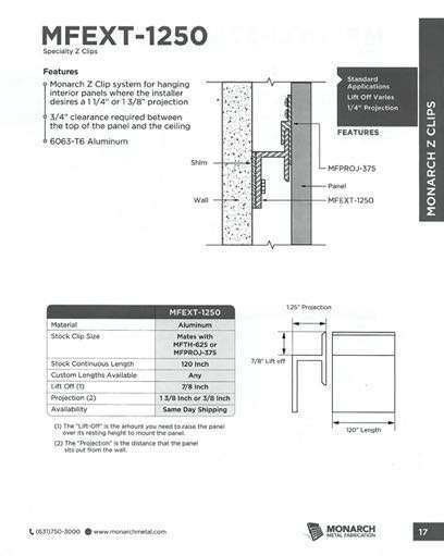
In order to accommodate the installation of acoustic backing material (e.g., our QuietWall backing material,) the installed panel should project off the panel by approximately an inch or more. This standoff will allow the placement of acoustical backing material behind the panel, for example by affixing the acoustic abatement material directly to the wall using an adhesive like a Loctite P11 type construction adhesive.
You can then proceed with your installation, for example by using a standoff Z-clip and Z-bar (See Diagram MFEXT1250.) Alternatively, furring strips can be used to provide a 1” standoff and low-profile Z-clips can be inserted. Installing the Z-clips on the wall then applying the acoustical fiberglass to the wall works best, with the panels hung on the existing Z-Clip installation, sandwiching the acoustical backing material between the wall and the back of the panel.
Tips for Horizontal Panel Installation: Although our panels are typically installed in a vertical orientation, they may also be suitable for horizontal installation subject to your ability to provide adequate installation safeguards. Panels can be mounted horizontally if proper support through an engineered wall system is provided during installation. To help you determine whether to attempt a horizontal installation, please consider the following installation information.
In vertical installations, the ridged design (i.e., the high ribbing of the Linear Line and Linear Sound panel,) of the RLS panels supports the panel, providing ridged support and stiffening the panel when installed, for example by being locked into French cleats. With this panel design, the high face ribbing of a Linear Sound panel is running perpendicular to the installation system to provide the ridged support.
Using the Linear Sound panels as an example, in a horizontal installation the high ribbing is instead running parallel to the installation system, with this greatly reducing structural support for the panel, impairing the rigidity of the panel. The result will be a wavy vertical appearance unless additional vertical support is provided.
To provide a successful horizontal installation, suitable vertical stiffening must be attached to the wall, or the panel, or preferably both, to provide a ridged vertical support. Consider affixing additional vertical supports to the wall, running perpendicular to the high face ribbing of the panel. One of the ways to achieve additional support is to insert vertical supports in-between the installation fasteners, and consider using spot cleats, pre-drilled and inserted into the core. Additional vertical support can also be applied to the back of the panel using stiffening bars on the back of the panel prior to installation. Stiffening bars are commonly used in such applications and can be low profile and well placed to avoid interference with the installation hardware.
Exercise great care in placement of the installation hardware because it is important for RLS panels to “top hang” in a horizontal installation such that the installation cleat located on the top is fully engaged with the panel, and the installation cleat on the bottom is also fully engaged, not “short” or pushing up on the panel from the bottom. If the panels are not properly seated and engaged with both the top and bottom cleats, the panel may come to rest on the bottom cleat, hence having a tendency for the entire panel weight to rest on the bottom cleat, with this causing a billowing or “pushing out ” of the panels. This is a particularly important requirement for panels with aggressive face cuts, such as the Linear Line and Sound panel products.
Additional Support for Horizontal Joints: Exercise care to support horizontally installed panels with furring strips applied to the joint areas of such an installation. This furring strip should force the panel proud off the wall, and line up with the protrusion of the Z-bars to counter the natural tendency of the panels to curve inward at the edges. Since the edges are running the length of a horizontal and edges are long, they may be visually intrusive if not supported.
4. Trim Options for Walls and Ceilings
